


Audi Q5 8R Virtual Cockpit-upgrade: volledige installatiegids voor 2009–2017 Q5 & SQ5
Hoe installeer je een Audi Q5 8R Virtual Cockpit op 2009–2017 modellen?
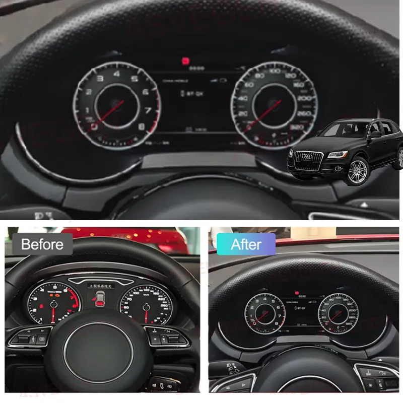
Kort antwoord
Voor een compatibele 2009–2017 Audi Q5 / SQ5 8R met het originele mechanische instrumentencluster, is de inbouwroute: de originele voertuigstatus documenteren, het fabriekscluster verwijderen, de vereiste originele elektronica overzetten naar de nieuwe digitale-clusterassemblage, de bijpassende kabelboom zonder knippen aansluiten, de update-USB toegankelijk houden, het cluster testen onder spanning vóór de definitieve afsluiting, en daarna de vereiste display- en brandstofkalibratiecontroles uitvoeren.
Dit is een voertuigspecifieke werkplaatsprocedure, geen universele compatibiliteitsbelofte. De exact geleverde clusterversie en de voertuigbasis bepalen nog steeds de uiteindelijk ondersteunde functies en menuroutes.
Deze pagina is een iKAGOO Audi Q5 8R Virtual Cockpit Retrofit installatiegids voor compatibele 2009–2017 Audi Q5 / SQ5 8R modellen met het originele mechanische instrumentencluster. Het is opgebouwd als een controleerbare werkplaatsprocedure, niet als een universele compatibiliteitsgarantie, en het mag niet worden gelezen als een belofte dat elke functie, waarschuwingsstatus of voertuigvariant identiek werkt.
Plug-and-Play grens: Plug-and-Play betekent geen knippen of splitsen van de originele voertuigkabelboom. Het vereist nog steeds demontage van het dashboard, overdracht van de originele printplaat, inspectie van de hulpprintplaat waar van toepassing, routing van de USB-kabel, controle van de instellingen en kalibratie.
Audi Q5 8R modeljaar focus: Deze gids is geschreven voor de Audi Q5 / SQ5 8R-generatie, doorgaans verkocht als 2009–2017 op de Europese en Noord-Amerikaanse markten. Hij is alleen van toepassing op compatibele voertuigen met het originele mechanische clustertraject. Elke gedeelde Audi / Volkswagen-instellingsreferentie mag alleen worden toegepast wanneer de meegeleverde Q5-clusterversie hetzelfde menupad gebruikt.
Welke Audi Q5 8R modellen dekt deze Virtual Cockpit installatiegids?
Direct antwoord
Deze installatieroute is geschreven voor compatibele eerste-generatie Audi Q5 / SQ5 8R voertuigen met het originele mechanische instrumentencluster. Voor iKAGOO hardware blijft het werkende geschiktheidsbereik in deze gids 2009–2017. Het voertuig moet nog steeds worden bevestigd aan de hand van foto's van het originele cluster en het dashboard voordat wordt besteld of gedemonteerd.
Audi verkocht de eerste-generatie Q5 onder verschillende motor-, uitvoerings- en marketingnamen in Europa en Noord-Amerika. Die namen zijn nuttig voor het identificeren van het voertuig, maar motornaam, uitvoeringsniveau of modelbadge alleen bewijst geen clustercompatibiliteit. De fysieke originele clusterroute is de beslissende referentie.
Noord-Amerika: Audi Q5 / SQ5 8R
- Audi Q5 8R / eerste-generatie Q5: Amerikaanse modeljaren 2009–2017.
- Veelvoorkomende Q5 namen: Q5 2.0T / 2.0 TFSI quattro, Q5 3.2 FSI quattro, Q5 3.0T / 3.0 TFSI quattro, Q5 TDI / 3.0 TDI clean diesel quattro, en Q5 hybrid quattro.
- Prestatiemodel: Audi SQ5 8R, in Noord-Amerika vaak geïdentificeerd als het 3.0 TFSI / 3.0T quattro-model.
- Uitvoeringsnamen die in de VS en Canada voorkomen: Premium, Premium Plus en Prestige. De uitvoeringsnaam vervangt niet de op foto's gebaseerde pasvormbevestiging.
- Niet deze generatie: Amerikaanse modeljaar 2018 en latere Q5-voertuigen behoren tot de volgende-generatieroute en mogen deze installatieprocedure niet gebruiken.
Europa: Audi Q5 / SQ5 8R
- Audi Q5 8R / eerste-generatie Q5: de eerste generatie werd in Europa geïntroduceerd in 2008; deze iKAGOO-gids hanteert een 2009–2017 bevestigde verkoop-/pasvormgrens. Een voertuig dat in 2008 is geregistreerd, vereist individuele bevestiging voordat deze gids wordt gebruikt.
- Veelvoorkomende benzinemodellen: Q5 2.0 TFSI, Q5 3.2 FSI, Q5 3.0 TFSI en Q5 hybrid quattro.
- Veelvoorkomende dieselmotoren: Q5 2.0 TDI en Q5 3.0 TDI quattro.
- Prestatie-uitvoeringen: SQ5 TDI, SQ5 TDI plus en, in de betreffende markten, SQ5 TFSI. Deze namen beschrijven de voertuigversie; het originele instrumentenpaneel moet nog steeds overeenkomen met de ondersteunde route.
- Carrosseriegeneratie-aanduiding: Q5 8R, Q5 Mk1, eerste generatie Q5, pre-facelift Q5 8R en facelift Q5 8R kunnen allemaal door eigenaren en werkplaatsen worden gebruikt.
Nuttige zoek- en identificatietermen: Audi Q5 8R virtual cockpit, Audi Q5 digitaal instrumentenpaneel, Audi Q5 LCD-cluster, Audi Q5 8R digitaal dashboard, Audi Q5 Mk1 virtual cockpit, Audi SQ5 8R digitaal cluster, Audi Q5 2009–2017 instrumentenpaneel retrofit.
Compatibiliteitsgrens: Deze namen zijn opgenomen zodat Europese en Noord-Amerikaanse eigenaren de juiste generatie kunnen identificeren. Ze zijn niet geen verklaring dat elke motor, uitvoering, landspecificatie of fabrieksoptie identieke elektronica gebruikt.
Wat moet worden bevestigd voordat er demontagewerk wordt uitgevoerd?
- Exact voertuigmodel en modeljaar.
- Origineel mechanisch instrumentenpaneel gefotografeerd terwijl het ingeschakeld is.
- Foto van het volledige dashboard en de instrumentenlijst.
- LHD- of RHD-configuratie.
- Eventuele waarschuwingslampjes of berichten die al aanwezig zijn vóór de retrofit.
- Eventuele eerder geïnstalleerde niet-originele elektronica, adapters of gewijzigde bedrading.
Demonteer niet eerst en bevestig later. De originele foto van het ingeschakelde instrumentenpaneel is de basis voor het vergelijken van waarschuwingen, de vorm van het cluster en de configuratie van het donorboard. Als het voertuig niet overeenkomt met de gedocumenteerde 8R mechanische-clusterroute, stop dan en bevestig de pasvorm voordat u doorgaat.
Welke instellingen moeten worden gecontroleerd voordat het Audi Q5 8R-fabriekscluster wordt verwijderd?
Direct antwoord
Voordat u het originele mechanische cluster verwijdert, documenteert u de huidige waarschuwingsstatus. Waar het originele menu deze functies biedt, stelt u de waarschuwing winterbanden en waarschuwing voor de voertuigsnelheidslimiet in op de maximaal beschikbare waarde en schakelt u vervolgens de waarschuwingsfuncties uit in het multifunctionele snelheidslimietmenu.
1. Leg de originele toestand vast
Schakel het contact in en fotografeer het cluster voordat u het demonteert. Leg de kilometerstand, het brandstofniveau en eventuele zichtbare waarschuwingslampjes of meldingen vast die later van belang kunnen zijn.
Waarom: Nadat het nieuwe display is geïnstalleerd, hebt u een betrouwbare voor/na-referentie nodig. Een waarschuwing die al aanwezig was, mag niet als een inbouwfout worden gediagnosticeerd.
2. Normaliseer de beschikbare waarschuwingsinstellingen
Ga naar het originele voertuigmenu. Stel de winterbandwaarschuwing en de snelheidslimietwaarschuwing in op de maximaal beschikbare waarde en schakel vervolgens de betreffende waarschuwingsfuncties uit waar het menu dit toestaat.
Voordat u verdergaat: Fotografeer de uiteindelijke menustatus zodat de installateur deze na het inschakelen kan vergelijken.
Versiegrens: De menubewoording kan per voertuigspecificatie verschillen. Als het geleverde voertuig niet hetzelfde instellingenpad toont, forceer dan geen andere Audi/VW-menuroute alleen omdat deze in een andere clusterversie voorkomt.
Hoe verwijdert u het originele mechanische instrumentencluster van een Audi Q5 8R?
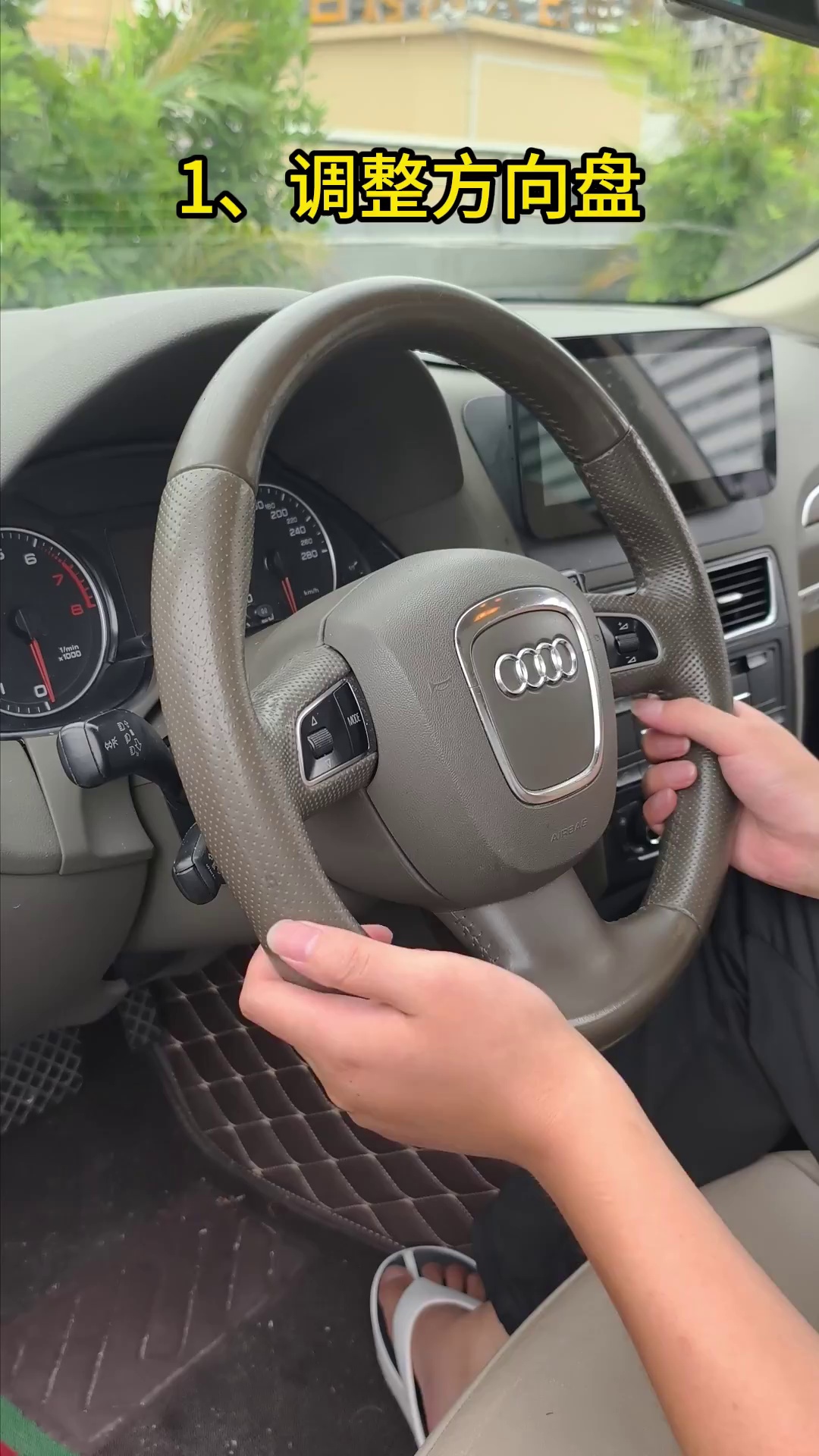
Laat het stuurwiel zakken en maak het onderste stofschild los
Zet het stuurwiel in de laagst haalbare stand om werkruimte voor het originele cluster te creëren. Maak de onderste stofkap / onderste sierlijst voorzichtig los in plaats van het cluster ertegenaan te trekken.
- Wel doen: creëer voldoende ruimte zodat het cluster naar voren kan bewegen zonder de sierlijstopening te schrapen.
- Controleer: de onderste kap moet vrij kunnen bewegen en mag niet achter de clusterrrand blijven haken.
- Vermijden: direct wrikken tegen het transparante clusterfront of een sierlijstrand forceren die nog niet is losgekomen.
- Stop als: de sierlijst biedt sterke weerstand; controleer de vastgehouden punten opnieuw voordat u meer kracht uitoefent.
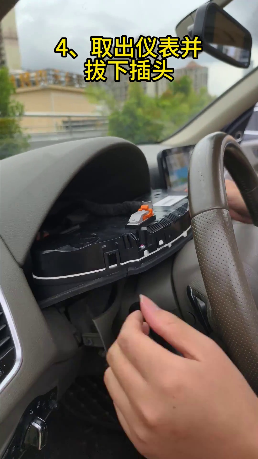
Verwijder de vastgehouden schroeven, trek het cluster naar voren en koppel de originele stekker los
Verwijder de originele vastgehouden schroeven. Ondersteun het cluster met beide handen, breng het in een gecontroleerde beweging naar voren en maak vervolgens de originele connector bereikbaar. Maak de connector los via het vergrendelingsmechanisme en niet door aan de kabelbundel te trekken.
- Wel doen: ondersteun het cluster terwijl het laatste bevestigingspunt wordt losgelaten.
- Controleer: de connector en contactpunten moeten recht en onbeschadigd lijken na het loskoppelen.
- Vermijden: de connector verdraaien, aan draden trekken of het verwijderde cluster met de voorkant naar beneden op een hard oppervlak leggen.
- Volgende: verplaats het complete originele cluster naar een schone, gevoerde werkbank omdat de elektronica ervan nodig is voor de inbouwroute.
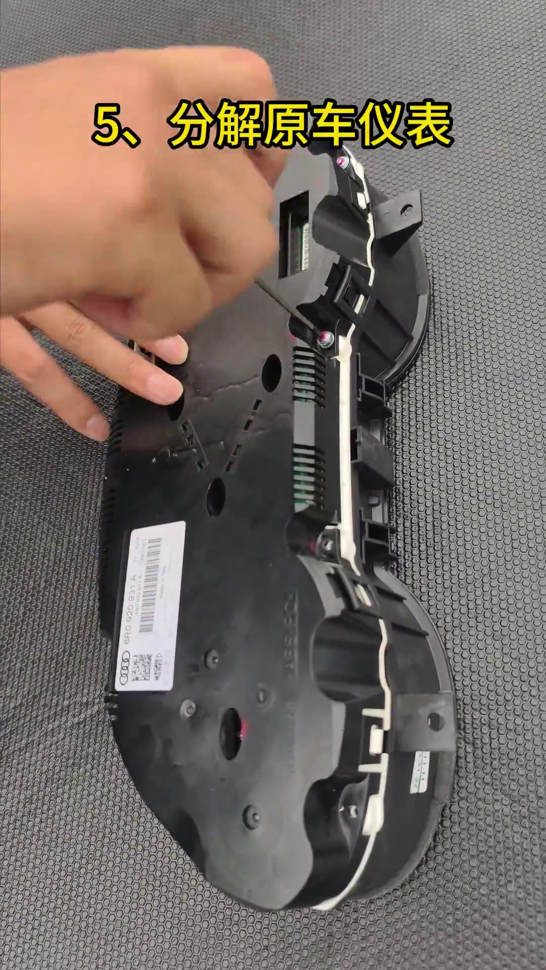
Hoe draag je de originele Audi Q5 8R cluster-elektronica over naar het digitale cluster?
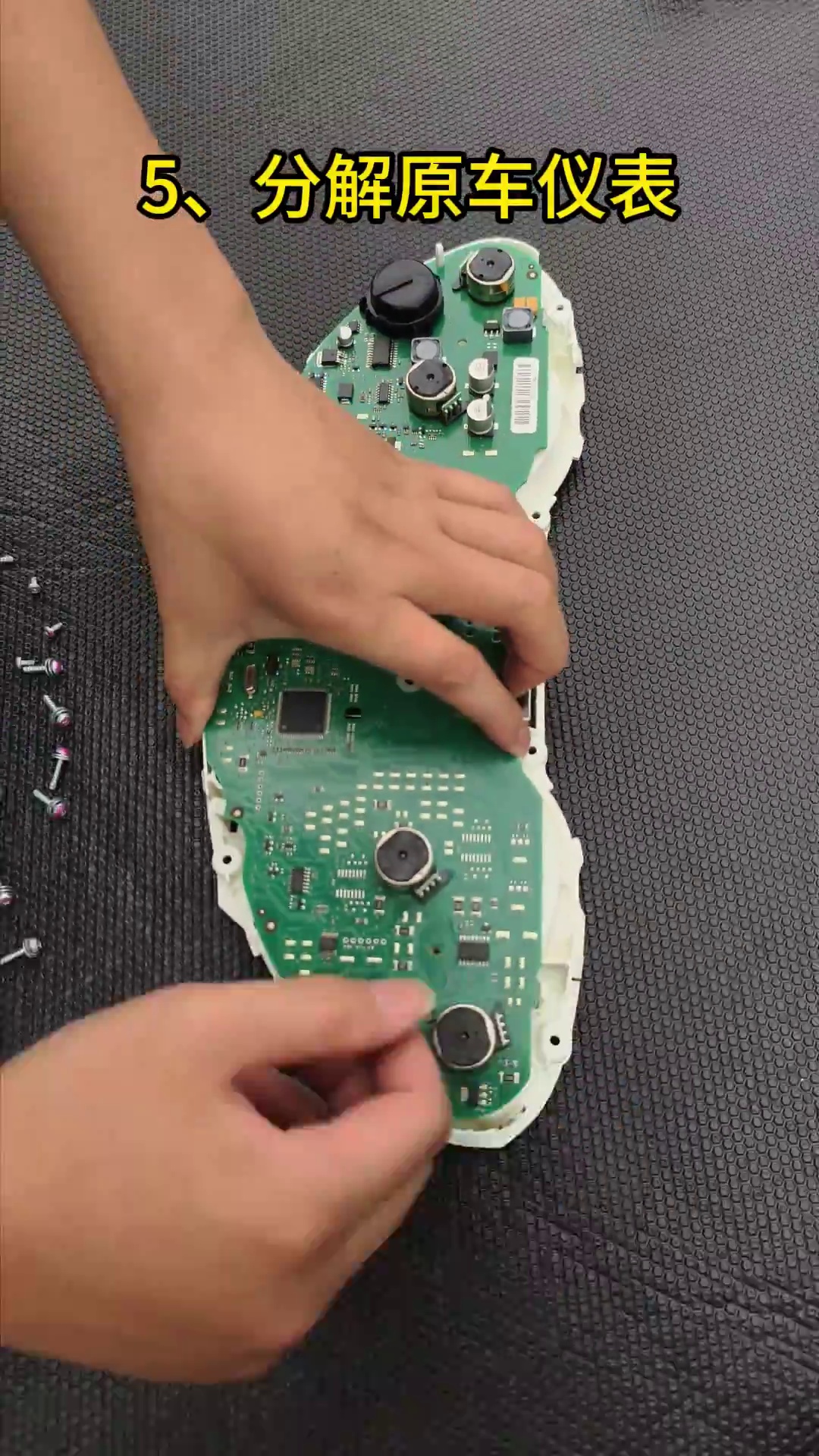
Open het donorcluster op een schoon, gevoerd en statisch veilig werkoppervlak
Plaats het originele mechanische cluster op een gevoerde werkbank. Voordat u de PCB aanraakt, ontlaadt u uw lichaamsstatische lading door een geaard metalen voorwerp aan te raken. Open de behuizing voorzichtig en houd verwijderde schroeven en behuizingsonderdelen gegroepeerd in hun oorspronkelijke volgorde.
- Hanteer de PCB aan de randen. Vermijd het aanraken van chips, gesoldeerde componenten en contactoppervlakken.
- Houd hardware georganiseerd. Meng geen schroeven van verschillende behuizingslocaties.
- Inspecteer vóór overdracht. Let op bestaande schade, verontreiniging of eerdere reparatiesporen.
- Stop als: de donorkaart is zichtbaar beschadigd of het cluster is gewijzigd op een manier die niet overeenkomt met de gedocumenteerde route.
Inspecteer het originele cluster op de kleine hulpkaart en draag deze over indien aanwezig
Sommige mechanische clusters met hogere specificatie bevatten een kleine hulp-printplaat achter het originele kleine display. Als uw donorcluster deze kaart heeft, moet deze worden geplaatst en vastgezet in de nieuwe LCD-clusterassemblage zoals aangegeven door de meegeleverde route. Als het donorcluster de kaart niet heeft, voeg er dan geen toe alleen omdat een ander voertuig deze heeft.
- Kijk eerst: inspecteer achter het originele kleine display voordat u donoronderdelen weggooit of sluit.
- Indien aanwezig: zet de kaart vast in de vereiste positie zodat deze niet kan bewegen in de nieuwe behuizing.
- Waarom: een weggelaten of losse hulpkaart kan in verband worden gebracht met onnauwkeurige brandstofindicatie of instrumentwaarschuwingen op toepasselijke versies.
- Vóór het sluiten: vergelijk de positie van de kaart met de referentieafbeelding en bevestig dat deze niet tegen het LCD of de bedrading drukt.
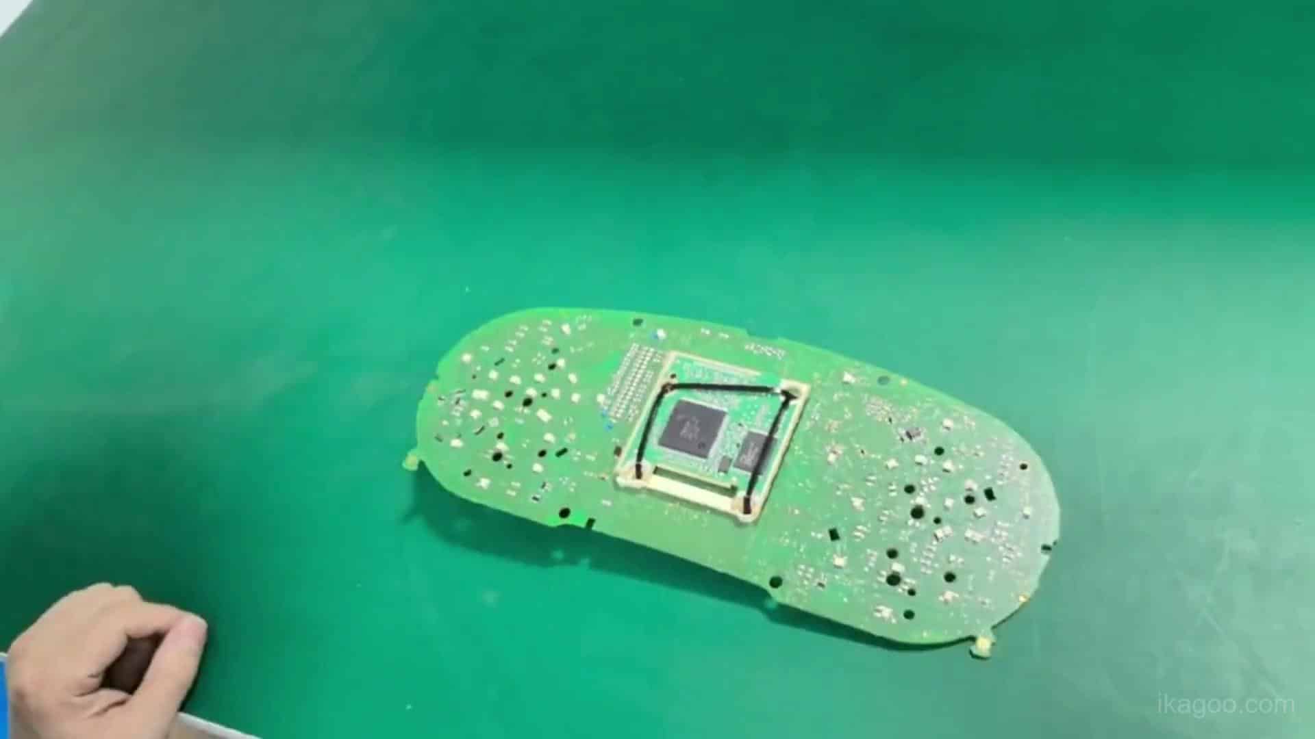
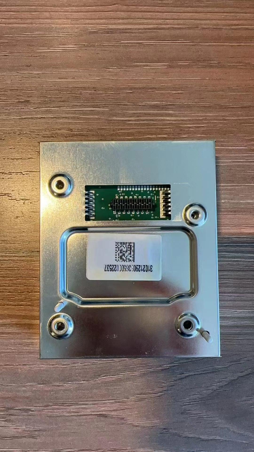
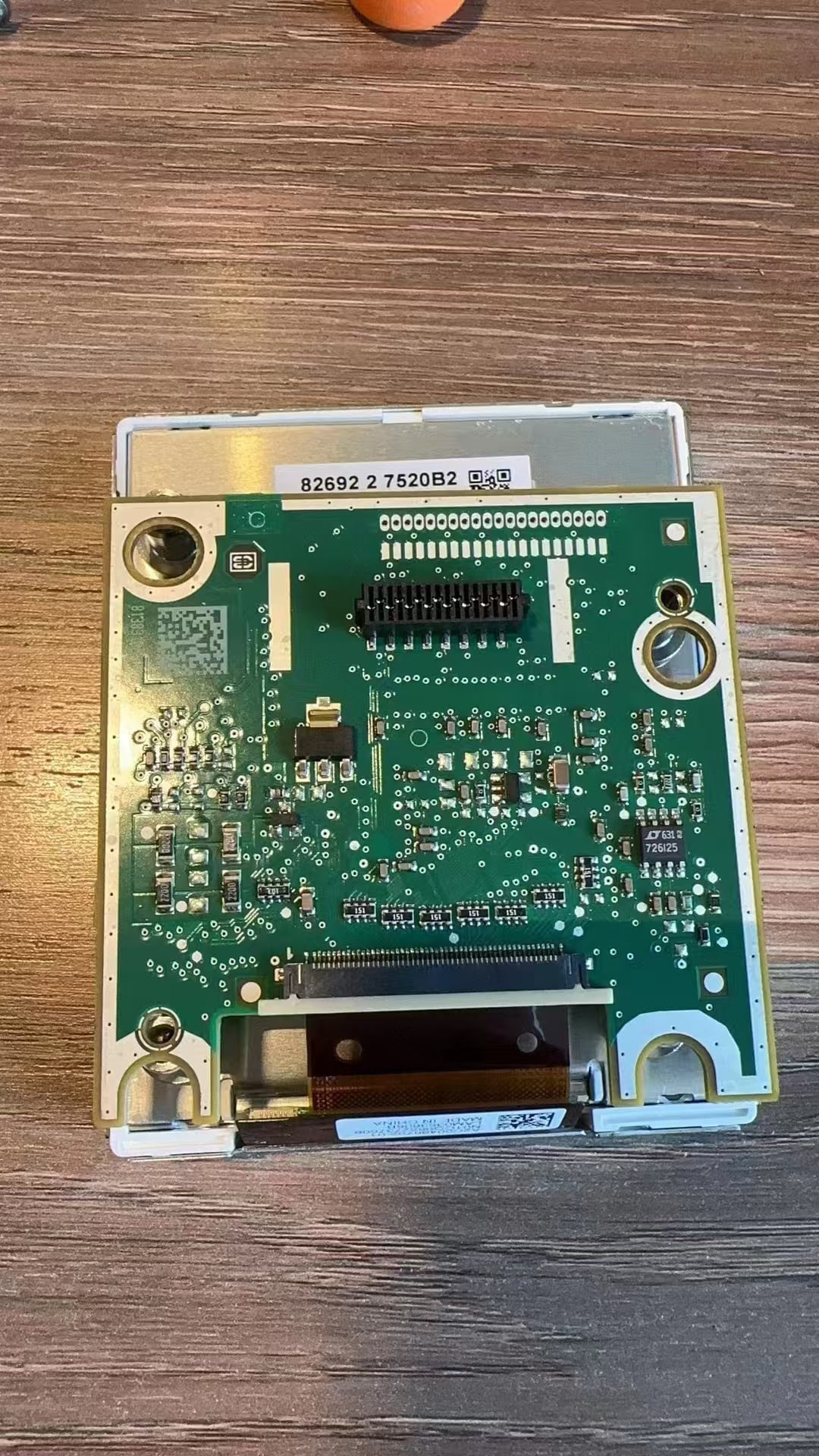
Draag de originele hoofdprintplaat over naar de nieuwe digitale-clusterbehuizing
Verplaats de behouden originele hoofdprintplaat naar de nieuwe digitale-clusterassemblage zonder deze te buigen of te draaien. Lijn de montage- en aansluitpunten uit voordat u druk uitoefent. Houd de PCB vlak en zorg ervoor dat de hulpkaartroute, indien van toepassing, al correct is behandeld.
- Plaats de kaart vlak: geen enkele hoek mag opgetild of onder spanning blijven.
- Sluit verbindingen volledig aan: laat een lintkabel, socket of aansluitpunt niet gedeeltelijk ingestoken achter.
- Houd draden vrij: geen enkele draad mag onder een PCB-rand of schroefpunt van de behuizing door lopen.
- Vóór het sluiten: inspecteer visueel de volledige omtrek van de printplaat en bevestig dat niets bekneld zit.
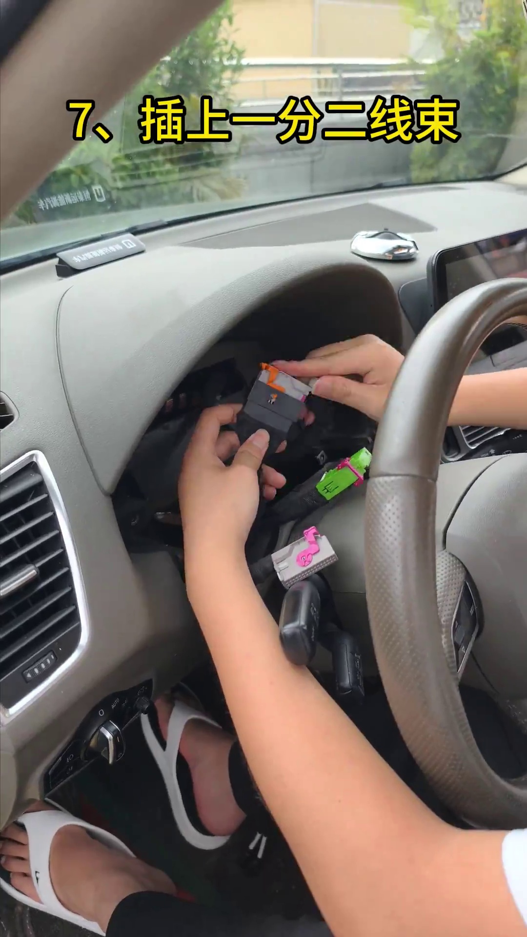
Sluit de bijpassende plug-and-play kabelboom aan en leid beide USB-kabels voordat de cluster wordt geplaatst
Sluit de meegeleverde bijpassende kabelboom aan op de juiste aansluitpunten zonder de originele voertuigbedrading te knippen of te splitsen. Lijn elke connector uit voordat u deze vastdrukt. Leid in dezelfde fase de twee meegeleverde USB-kabels naar een toegankelijke opbergruimte lager bij het stuurwiel waar praktisch.
- Plug-and-play betekent: geen knippen of splitsen van de originele voertuigkabelboom; demontage van het dashboard en overzetten van elektronica zijn nog steeds nodig.
- Kabelboomcontrole: elke connector moet volledig vastzitten en de kabelboom moet voldoende speling hebben om spanning te voorkomen.
- USB 1: houd de bedrade software-update-USB toegankelijk.
- USB 2: houd de ondersteunde bedrade mirroring / projection-USB toegankelijk waar de meegeleverde clusterversie deze functie biedt.
- Vermijden: het beknellen van de kabelboom of USB-kabels achter een scherpe behuizingsrand wanneer de cluster terug in het dashboard wordt geduwd.
Waar moeten de USB-kabels van het Audi Q5 digitale cluster na installatie worden gelaten?
Direct antwoord
Begraaf de meegeleverde USB-kabels niet permanent achter het dashboard. Houd de software-update-USB en, waar ondersteund door de meegeleverde versie, de bedrade projection / screen-mirroring-USB bereikbaar vanuit een praktische opbergruimte lager bij het stuurwiel.
Vóór definitieve plaatsing: trek elke USB-kabel voorzichtig vanaf het geplande toegangspunt en bevestig dat deze vrij blijft. Laat voldoende speling zodat de connector niet wordt belast wanneer de cluster op zijn plaats wordt geduwd.
Waarom dit belangrijk is: toekomstige softwareondersteuning of een ondersteunde bedrade projection-controle zou geen onnodige demontage van het dashboard moeten vereisen.
Versiegrens: USB-functies kunnen variëren per meegeleverde hardware/softwareversie. Behoud de fysieke toegangsroute, maar claim alleen de USB-functies die zijn bevestigd voor de exact meegeleverde cluster.
Wat moet worden getest voordat het Audi Q5 8R dashboard wordt gesloten?
Schakel het digitale cluster in voordat het definitief wordt vastgezet
Met de cluster aangesloten maar nog toegankelijk, zet het contact aan en laat het LCD opstarten. Sluit de onderste afwerking nog niet. Vergelijk het nieuwe display met de foto's die vóór demontage zijn genomen.
- Opstarten: bevestig dat het LCD normaal inschakelt en niet herhaaldelijk opnieuw opstart.
- Schermconditie: controleer op lijnen, donkere drukplekken, scheuren, abnormale heldere plekken of zichtbare schade aan het paneel.
- Waarschuwingen: vergelijk waarschuwingslampjes/berichten met de originele registratie van het ingeschakelde cluster.
- Basisvoertuiggegevens: bevestig dat de zichtbare informatie die wordt verwacht voor de bevestigde voertuigroute aanwezig is voordat u het dashboard sluit.
- Als er een nieuw probleem verschijnt: stop en controleer opnieuw de overgedragen hoofdbord, hulpbord indien van toepassing, kabelgeleiding en connectorplaatsing voordat u software overweegt.
LCD-veiligheid: druk niet op het beeldschermoppervlak tijdens het testen of plaatsen. Barsten en donkere drukvlekken zijn fysieke behandelingsproblemen en kunnen niet door software worden gerepareerd.
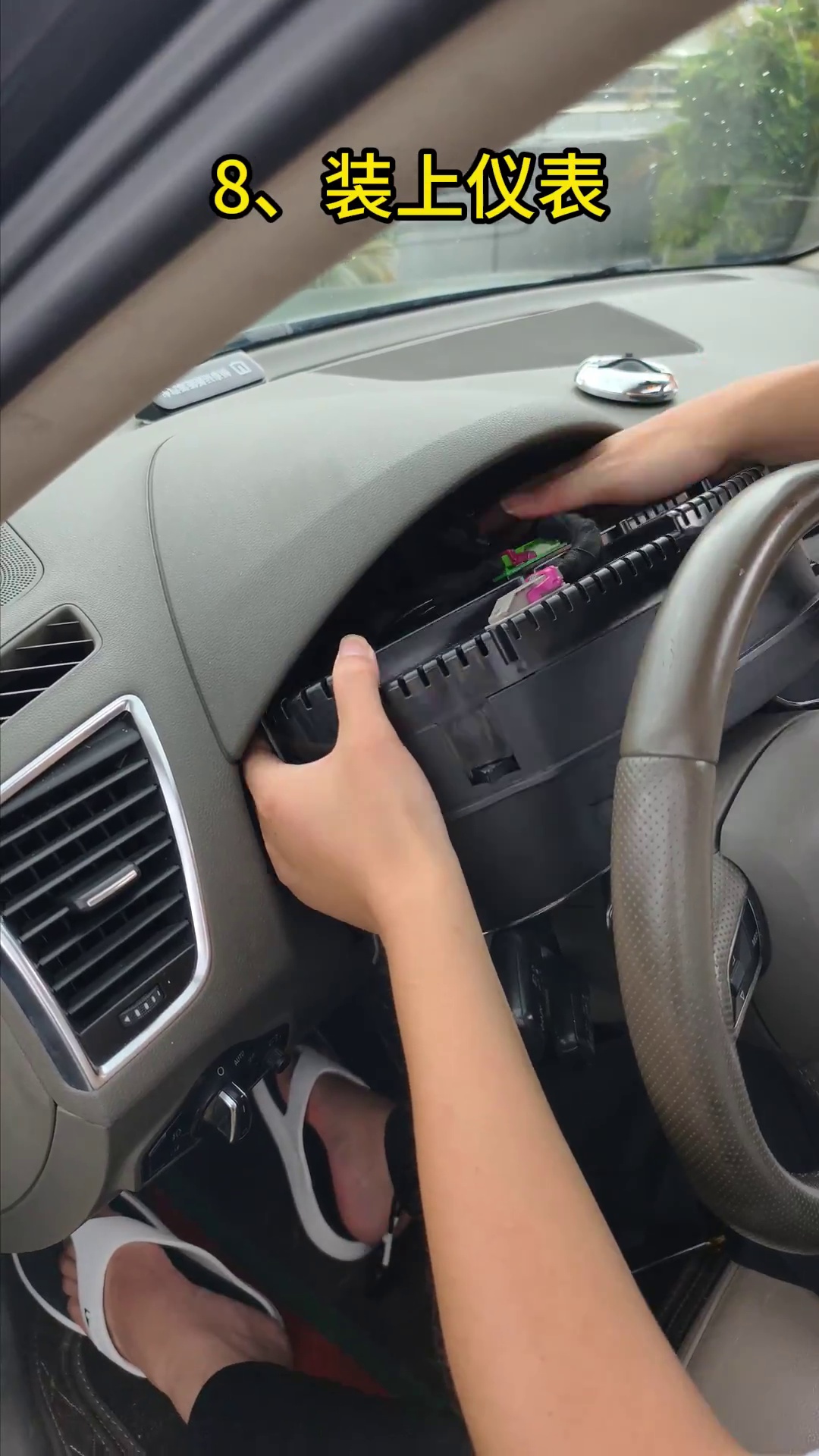
Plaats het cluster gelijkmatig, monteer de bewaarde schroeven terug en sluit het onderste sierstuk
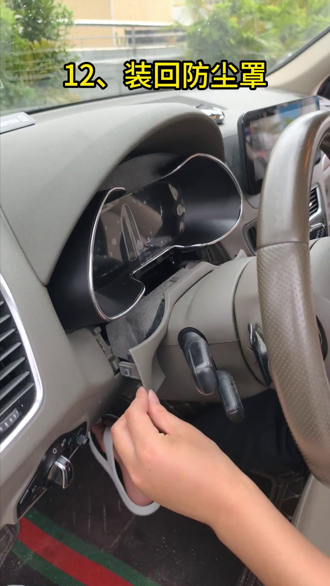
Pas nadat stap 07 is geslaagd, mag het cluster naar zijn definitieve positie worden verplaatst. Leid de kabelboom en USB-kabels erachter langs zonder ze scherp te vouwen. Monteer de bewaarde bevestigingsschroeven terug en plaats vervolgens de onderste stofkap / sierstuk terug.
- Montage: het digitale cluster moet gelijkmatig in de opening zitten zonder dat één zijde naar binnen wordt gedwongen.
- Kabelvrijheid: geen kabelboom of USB-kabel mag tussen de behuizing en de dashboardstructuur bekneld raken.
- Onderste stofkap: pas alleen aan waar de werkelijke speling dit vereist; verwijder niet meer materiaal dan nodig is.
- Laatste druktest: het teruggeplaatste sierstuk mag niet tegen het LCD-oppervlak of de clusterbehuizing drukken.
- Laatste contacttest: schakel het voertuig na het sluiten opnieuw in en bevestig dat de weergavestatus niet is veranderd.
Hoe kalibreert u de brandstofmeter na een Audi Q5 8R digitale cluster-retrofit?
Direct antwoord
Vul de brandstoftank volledig, rijd een paar honderd meter en open dan Rijgegevens → Bijvulbare hoeveelheid. Gebruik de weergegeven bijvulbare hoeveelheid als de waarde die wordt ingevoerd onder Instellingen → Configuratiekalibratie → Brandstoftankcapaciteit. Na succesvolle kalibratie moet de bijvulbare hoeveelheid terugkeren naar 0 en moet de brandstofmeter vol aangeven.
- Vul de brandstoftank van het voertuig volledig.
- Rijd een paar honderd meter zodat de weergavestatus wordt bijgewerkt.
- Open Rijgegevens → Bijvulbare hoeveelheid en noteer de weergegeven waarde.
- Open Instellingen → Configuratiekalibratie → Brandstoftankcapaciteit.
- Voer de waarde van de bijvulbare hoeveelheid in die in de vorige stap is geregistreerd.
- Controleer de weergave opnieuw. De bijvulbare hoeveelheid moet terugkeren naar 0 en de meter moet een volle tank aangeven.
Als het resultaat nog steeds onjuist is: bevestig bij voertuigen waarvan het donorcluster het kleine hulpbord bevatte dat het bord correct is behouden en bevestigd voordat u herhaaldelijk kalibratiewaarden wijzigt.
Laat Physical Light uitgeschakeld als deze instelling in de meegeleverde clustersoftware verschijnt
Direct antwoord: Als de meegeleverde software een Fysiek licht optie toont, laat deze uitgeschakeld tenzij de gedocumenteerde correctieroute specifiek vereist dat u deze aanvinkt, omdat een onjuiste instelling het weergavegedrag van de richtingaanwijzer kan beïnvloeden.
Pas de grafische weergave van het voertuigmodel alleen aan nadat de hardwaremontage is bevestigd
Als de grafische weergave van het kleine voertuigmodel niet overeenkomt met het echte voertuig, voer Instellingen → Voertuigmodelselectie. Kies waar beschikbaar het overeenkomende model. Schakel na selectie het voertuig uit, vergrendel het en wacht een paar minuten. Dit wijzigt alleen de zichtbare modelgrafiek. Het vervangt geen bevestiging van hardwarecompatibiliteit. Waarom het belangrijk is: Lezers verwarren vaak een mismatch van het displaymodel met een mismatch van de hardware. Het menu wijzigt alleen het zichtbare grafische traject. Hoe controleren: Wijzig de modelgrafiek, vergrendel het voertuig en wacht een paar minuten voordat u de nieuwe weergavestatus controleert. Indien overgeslagen: De klant kan aannemen dat het hardwaretraject onjuist is, terwijl alleen het zichtbare auto-modelpictogram moet worden aangepast.Laatste controlelijst voordat de Audi Q5 weer normaal wordt gebruikt
| Controlepunt | Wat te controleren | Als het niet slaagt |
|---|---|---|
| Display opstarten | De LCD start normaal tijdens de eerste inspectie bij het inschakelen. | Stop de definitieve sluiting en controleer opnieuw de bord-overdrachtsfase en de connectorpositionering. |
| Hulp klein bord indien van toepassing | Als het originele cluster de kleine printplaat had, bevestig dan dat deze correct is gerepareerd en geïnstalleerd. | Open de assemblage opnieuw en corrigeer de positie van de hulpprintplaat voordat u software de schuld geeft. |
| Schermconditie | Er zijn geen lijnen, donkere drukplekken, scheuren of glasschade zichtbaar. | Stop met het hanteren van het display; fysieke schade aan het paneel wordt niet door software hersteld. |
| Vergelijking van zichtbare waarschuwingen | Vergelijk de huidige waarschuwingen met het record van vóór de installatie. | Onderzoek nieuw verschenen waarschuwingen in plaats van ze als verwacht te beschouwen. |
| Brandstofdisplay | Bevestig na het tanken het gedrag van de meter en de logica voor de bijvulbare hoeveelheid. | Controleer indien van toepassing de kleine printplaat en voer vervolgens de kalibratie van de brandstoftankcapaciteit uit. |
| Richtingaanwijzergave | Bevestig het gedrag van de linker- en rechterrichtingaanwijzerweergave. | Controleer of Physical Light niet onjuist is ingeschakeld als deze instelling in de meegeleverde softwareroute verschijnt. |
| Toegang tot USB-kabel | De update-USB en ondersteunde projectie-USB blijven toegankelijk. | Corrigeer het kabelverloop voordat u het dashboard volledig sluit. |
| Passing en afwerking | De cluster zit gelijkmatig en de onderste afwerking drukt niet tegen het display. | Open de afwerkingsfase opnieuw en controleer de speling alleen waar aanpassing daadwerkelijk nodig is. |
| Ondersteunde functies | Verifieer alleen de functies die zijn bevestigd voor het meegeleverde voertuig en productpad. | Ga niet uit van universeel behoud van functies; vergelijk met de bevestigde basislijn. |
| Foto van softwareversie | Bewaar een foto van het scherm met de geïnstalleerde versie vóór een latere update. | Pas online- of USB-updatepakketten niet blindelings toe op een niet-geregistreerde versie. |
Hoe deze Audi Q5 8R installatiegids is opgesteld en geverifieerd
Dit artikel wordt onderhouden door de Het technische team van iKAGOO voor de eerste generatie Audi Q5 / SQ5 8R digitaal cluster ombouwroute die op deze pagina is gedocumenteerd. De instructies zijn gebaseerd op de voertuigspecifieke installatiefoto's, donorboard-overdrachtsreferenties, hulpprintvoorbeelden, videocontrolepunten, eerste-inschakelingscontroles en kalibratiestappen na installatie die in de gids worden getoond.
Eerstelijns installatiebewijs
Het artikel gebruikt daadwerkelijke Q5 8R installatiefase-afbeeldingen die het verwijderen van het cluster, het openen van het donorcluster, het overzetten van de originele printplaat, het aansluiten van de kabelboom, het testen bij inschakeling en het terugplaatsen van de onderste afwerking omvatten.
Compatibiliteit wordt niet afgeleid uit een badge
Q5, SQ5, TFSI, TDI, quattro, Premium, Premium Plus of Prestige worden niet automatisch als bewijs van compatibiliteit beschouwd. iKAGOO controleert het bouwjaar van het voertuig, het originele ingeschakelde cluster, de dashboardindeling en de LHD/RHD-configuratie.
Bekende beperkingen worden openlijk vermeld
Gedeelde Audi/VW-menuverwijzingen, USB-projectiegedrag, updateroutes en behouden functies kunnen per geleverde versie verschillen. De gids scheidt bevestigde installatielogica van versieafhankelijk gedrag.
Beoordeeld: 2 september 2026
Toepassingsgebied: compatibele Audi Q5 / SQ5 8R mechanische-cluster ombouwroute, met een 2009–2017 iKAGOO montagegrens.
Redactionele regel: als het exacte voertuig of het geleverde cluster niet overeenkomt met een gedocumenteerde route, draagt het artikel de installateur op om te stoppen en te verifiëren in plaats van compatibiliteit aan te nemen.
Ondersteund Audi / Volkswagen Digital Cluster Upgrade Package Route
FixMyDash is bedoeld voor de aankoop van ondersteunde Audi / Volkswagen digitale cluster software-upgradepakketten en aan het pakket gerelateerde ondersteuning. Het is een aparte ondersteuningsroute voor compatibele bestaande digitale clusters. Het is geen hardware-reparatieservice. Het belooft niet om schade aan het scherm, beschadigde printplaten, bedradingsfouten, onjuiste installatie, communicatiefouten of niet-gerelateerde voertuigproblemen te repareren. Ondersteund Upgrade-pakket kopen Bekijk de online / USB-updategidsHebt u het bijpassende Audi Q5 8R Digital Instrument Cluster nodig voor 2009–2017?
Klanten die op zoek zijn naar het complete iKagoo Audi Q5 8R digitale instrumentcluster hardwarepad voor compatibele 2009–2017 Audi Q5 / SQ5 8R-modellen moeten vóór het bestellen de bijbehorende productpagina en de bevestiging van de passendheid gebruiken. Bekijk Audi Q5 Digital Instrument Cluster Product Controleer compatibiliteit met iKagooAudi Q5 8R Virtual Cockpit Installatievragen
Is deze gids voor Europese en Noord-Amerikaanse Audi Q5 8R modellen?
Ja, de gids is geschreven rond de eerste generatie Audi Q5 / SQ5 8R mechanische-cluster route die door eigenaren in Europa en Noord-Amerika wordt gebruikt. De iKAGOO montagegrens op deze pagina blijft 2009–2017. Amerikaanse modeljaren 2018 en latere Q5-voertuigen zijn een andere generatie. Europese voertuigen die voor het eerst in 2008 zijn geregistreerd, vereisen individuele bevestiging voordat deze 2009–2017 hardwareroute wordt gebruikt. Motor- of uitvoeringsaanduidingen zoals TFSI, TDI, quattro, Premium, Premium Plus, Prestige of SQ5 vervangen niet de fotobevestiging van het originele cluster.








Add comment
Je moet ingelogd zijn op om een reactie te plaatsen.